Welcome
to the EPE Online
Desoldering
Guide
Photo Gallery
|
|
|
|
Return
to Main Guide | Copyright
| EPE Online Home Page
Soldering Photo
Gallery
|
|
| De-soldering
is required when electronic components need to be removed from a circuit,
usually because they are faulty. It may sometimes be necessary during testing
or assembly, if a wrong part has been fitted or a modification has to be
made. In the field, it's not uncommon for faulty components to be swapped
out, or poor joints (perhaps "dry" joints) to need re-making properly,
months or years after manufacture. Experienced engineers can often diagnose
a particular faulty joint immediately, because they may have seen the same
problem on similar equipment before, especially if it has a "reputation".
A proper desoldering technique can soon be acquired with practice - all
you need to do is buy some scrap boards to have a go with, and desolder
to your heart's content!
The photo sequence
below illustrates the basic steps for desoldering a printed circuit board,
in order to remove a faulty part. Both a desoldering pump as well as desolder
braid are illustrated. Some real-life examples of poor soldering are shown
too, in my Black Museum of Bad Soldering!
Remember that
"Practice-makes-Perfect", and in the long run it costs less to get
it right than it does to get it wrong! |
|
Enjoy!
-- Alan Winstanley.
|
|
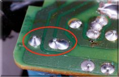 |
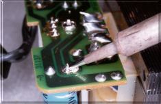
The
two solder joints to be desoldered, to enable a faulty component to be
removed. |
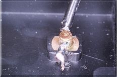
| If
using a desoldering pump, apply the iron first to melt the solder (1-2
seconds). Ensure the pump is 'primed' and ready to go... |
|
 |
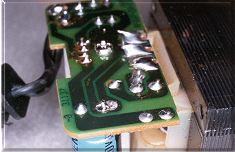
The
nozzle of the desoldering pump is applied to the molten solder and the
spring-loaded plunger is then released, drawing the solder up into the
pump. Repeat if needed. |
| The
first joint, now desoldered. The second joint will be desoldered using
braid... |
|
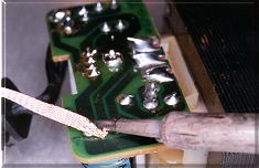 |
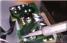
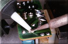
Select
a suitable width of braid, and press it down onto the COLD joint using
the hot tip of the iron. |
| Molten
solder is drawn up by capillary action into the braid. Care not to overheat,
or 'drag whiskers' of solder over the board, nor let the braid solidify
on the joint! |
|
 |
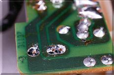
The
component dropped out of the board after desoldering. Sometimes, it may
need persuading with pliers.... |
| Close-up
shot of both joints, now desoldered and ready for the replacement part
to be fitted. |
|
|
The Black
Museum of Bad Soldering
|
| The following
are all genuine examples of bad soldering which have not been retouched
or reworked in any way. |
|
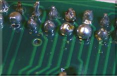 |
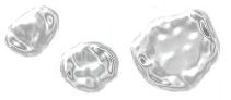
Tenfold
excess of solder, and (extreme left) incomplete joint with poor coverage.
There is no need to add more solder "for luck". |
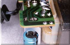
| One
example of several dry joints found within a commercial PSU adaptor for
a computer peripheral. |
 |
 |
Hmmmm...
this joint looks somewhat suspect as well... |
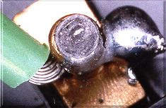
| A
close-up reveals the terrible standard of soldering (and quality control),
with a fracture visible on this ground/ earth joint. |
 |
 |
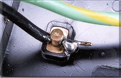
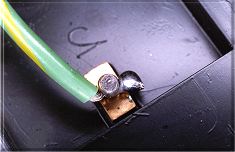
How
not to make a mains voltage soldered joint. This went "dry" and starting
arcing, nearly zapping the equipment. It is also a fire hazard. |
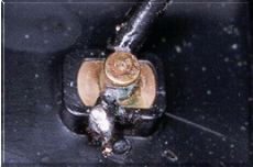
| The
same mains connection, the wire merely being 'tacked on' with a blob of
solder. |
|
|
| All
photos are Copyright © Alan Winstanley 1997. You may download them
for personal use, or for training or educational purposes only. They may
not be used on a commercial or sponsored web site without the prior permission
of the author (conditions apply). If you wish to use these pictures for
any commercial reasons, e.g. to enhance any commercial product, enframe
in any external commercial web site or apply for any other commercial use,
you must seek the author's prior approval first (email Alan Winstanley
at alan@epemag.demon.co.uk).
Very high resolution photos with licence for reproduction are also available
on CD from the author, on payment of a royalty. Please enquire if you have
similar macro photography assignments you would like to be quoted for and
undertaken.
For any interested
photographers: the photographs were taken by the author using a Minolta
X-700 SLR with 50mm Minolta MC manual-focus macro lens at f11-16, coupled
to a Minolta Auto 80PX macro ring flash gun. Film was 3M Colour Print 200.
The prints were scanned using an HP ScanJet 6250 flatbed scanner, and enhanced
using JASC Paintshop Pro 5 with filters, before uploading. |
|